GD&T (Geometric Dimensioning and Tolerancing) is basically a system which is used to define and communicate engineering tolerances. In this method, the geometry of mechanical parts is precisely defined. It allows engineers, designers, and fabricators to communicate engineering tolerances and accurately and precisely define a physical dimension or property of a material or a measured value.
x
c
a
d
d
c
e
n
t
r
e
Quick Links


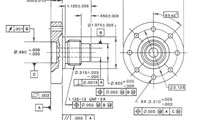
Geometric Dimensioning & Tolerancing
GD&T
Why to learn?
Learning GD&T will be helpful for one to precisely define the nominal geometry of parts and assemblies. GD&T is widely used in automotive, aerospace, electronic, and commercial design and manufacturing industries.
Knowledge and exposure of GD&T course which consists of dimensions, symbols, tolerances, definitions, rules, and conventions. GD&T is an important skill for engineers, designers and other CAD users.
Learning Objectives:
CADD Centre will help you to ace the associated features of GD&T:
- Dimensioning Specifications: Helpful for defining the nominal, as-modeled or as-intended geometry of parts.
- Tolerancing Specifications: Helpful for defining allowable variation for form and the size of individual features and allowable variation in orientation and location between features.
- Geometric Characteristics: Engineers can use symbolic language for engineering drawings & computer generated 3D solid models to explicitly describing nominal geometry and its acceptable variations. The geometric symbols include straightness, circularity, flatness, cylindricity, surface, the profile of a line, perpendicularity, and angularity.
Learning Outcome:
- Student will be able to communicate engineering configuration to all stakeholders: right from designers to manufacturers through mechanical drawings.
- Student will be able to tell manufacturing team what degree of accuracy and precision is needed on each controlled feature of parts.
- Student will know to define the acceptable variation in form and possible size of individual features, and acceptable variation between features.
- Student will know how to provide clear & concise techniques to define a reference coordinate system on a module or assembly which can be used throughout the manufacturing and inspection processes.
- Student will know about the proper application of geometric dimensioning, accepted and logical mechanical design process and design for manufacturing considerations.
- Student will know how to describe complex geometry requirements on a component or assembly using the standard symbols of GD&T.
- Student will know how to accurately and quickly define design, manufacturing and inspection requirements.
- Student will know how to simplify the design of cost-saving functional check gages, manufacturing fixtures, and jigs.